Capture Range (Pull-in Range)
Capture range, also called pull-in range, is the range of input frequencies over which a phase-locked loop (PLL) or similar synchronising circuit can pull itself into lock starting from an unlocked state. In semiconductors the term is used when designing and testing clock generators in SoCs and clock and data recovery (CDR) circuits in high-speed serial receivers.
Also called: pull-in range, acquisition range
Diagram
Capture range vs lock range
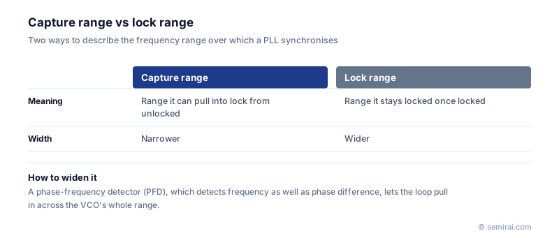
The lock range, or hold range, is the range over which a PLL that is already locked stays locked as the input frequency is slowly moved. Once locked, a loop holds on more easily than it can acquire, so the capture range is usually narrower than the lock range and lies inside it. A loop whose input starts within the capture range will lock by itself; one whose input starts outside it may never lock, even if it would stay locked there.
The width of the capture range depends on the phase detector and the loop filter. With a simple phase detector such as a mixer or an XOR gate, the loop can only pull in over a range of roughly the order of its loop bandwidth.
How designers widen it
A phase-frequency detector (PFD) detects frequency difference as well as phase difference. When the frequencies differ, it drives the voltage-controlled oscillator (VCO) steadily in the right direction, so the loop can pull in over the whole tuning range of the VCO. This is why PFDs with charge pumps are standard in clock-generating PLLs.
In CDR circuits, which recover a clock from incoming data, the phase-tracking loop usually has a narrow capture range. A common design first brings the VCO close to the target frequency using a reference clock or a frequency detector, then hands over to the phase-tracking loop. Too narrow a capture range can cause failures to lock at power-up or after temperature changes.
The same term is used for control loops such as alignment in lithography tools, meaning the range of initial error within which the system can still find and lock onto its target.
Japanese companies involved
- Renesas Electronics supplies clock generators and timing devices built around PLLs, as well as microcontrollers and SoCs that use on-chip PLLs.
- Renesas Electronics · Microcontrollers, automotive SoCs, analog and power chips
FAQ
Can widening the loop bandwidth increase the capture range?
Yes, but at a cost. A wider loop pulls in over a wider range and settles faster, but it also passes more reference noise and spurs to the output, increasing jitter. Designers often use a wide bandwidth during acquisition and narrow it after lock.
How is capture range measured?
Starting with the loop unlocked, the input frequency is set at various offsets from the free-running frequency, and the test records whether the loop acquires lock. The edges of the region where it does are the capture range limits.
Related pages
Sources
Last updated: November 2, 2026