Comparator
A comparator is a circuit that compares two input voltages and outputs a digital high (1) or low (0) depending on which is larger. It is the most basic boundary between the analog and digital worlds, turning a continuous voltage into a two-level signal that logic circuits can use.
Also called: voltage comparator, Schmitt trigger
Diagram
How a comparator works
A comparator amplifies the input difference so strongly that its output swings fully to the supply or to ground. Its structure resembles an op-amp, but it is designed to run without feedback, with emphasis on decision speed (propagation delay) and on an output that drives logic directly. Key specifications are propagation delay, input offset voltage, hysteresis width and supply current.
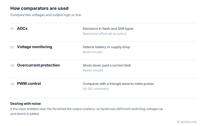
If the input sits near the reference and carries noise, a plain comparator's output can flip rapidly back and forth, a problem called chattering. Adding hysteresis, so that the switching threshold is slightly higher on the way up than on the way down, prevents it. A comparator with hysteresis is called a Schmitt trigger.
Where comparators are used
Data converters are a major use. A flash ADC uses 2^n − 1 comparators to convert to n bits in a single step, while a successive-approximation (SAR) ADC uses one comparator and decides each bit in turn from the most significant down. Fast, precise ADCs use latched comparators that settle their decision within a clock phase.
Comparators also watch supplies and protect circuits: under-voltage lockout (UVLO) stops a circuit when the supply drops, overcurrent protection shuts down a power stage when current exceeds a limit, and zero-cross detection finds where an AC waveform crosses zero. In PWM control, a comparator compares an error signal with a triangle wave to create the pulses that drive a DC-DC converter. In digital logic, a circuit that compares two numbers is also called a comparator.
Japanese companies involved
- ROHM and Renesas Electronics make comparators and the power management ICs that use them internally.
- ABLIC specialises in small analog ICs including voltage detectors, which are comparators with a built-in reference used to monitor supply voltage.
- ROHM · SiC and silicon power devices, analog ICs
- Renesas Electronics · Microcontrollers, automotive SoCs, analog and power chips
FAQ
What is hysteresis in a comparator?
It is a deliberate difference between the input voltage that switches the output from low to high and the voltage that switches it back. Noise smaller than this difference cannot make the output flip, so the output changes once cleanly when the input crosses the threshold.
How many comparators does a flash ADC need?
An n-bit flash ADC needs 2^n − 1 comparators, so an 8-bit converter needs 255. That is why flash converters are fast but limited to low resolution, while SAR converters use one comparator over several steps.
Related pages
Sources
Last updated: November 13, 2026