Double Pulse Test
The double pulse test is the standard method for measuring the switching characteristics of power semiconductors, including switching speed, turn-on and turn-off losses and diode reverse recovery, under conditions close to a real inverter. A simple circuit with an inductor and a freewheeling diode is driven by two gate pulses in a row.
Also called: DPT, double-pulse testing
Diagram
How the test works
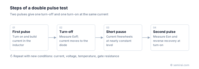
The test circuit is a half bridge: the device under test, an inductor as the load and a freewheeling diode (often the body diode or the opposite switch of the same type). When the first pulse turns the device on, current builds up in the inductor. The length of this pulse sets how much current is reached, so it is chosen to match the current at which the device is to be measured.
The end of the first pulse is the turn-off measurement point; the inductor current then continues through the diode. After a short pause, during which the current stays almost constant, the second pulse turns the device on again. That edge is the turn-on measurement point, and it also shows the reverse recovery of the diode. The method gives one turn-off and one turn-on at nearly the same current, while the device barely heats up, so temperature can be controlled with a hot plate or chamber.
Getting accurate results
Multiplying the measured voltage and current waveforms and integrating over each transition gives the switching energies Eon and Eoff. The test is repeated across current, voltage, temperature and gate resistance, and it is used to choose gate-driver settings that balance loss against noise.
Fast SiC and GaN devices switch in tens of nanoseconds or less, so the measurement setup matters. Small parasitic inductance in the loop causes large overshoot and changes the waveforms. Accurate results need a compact layout, wide-bandwidth voltage and current probes, and careful alignment of the probes' time delays, because even a nanosecond of skew distorts the calculated loss.
Japanese companies involved
- Advantest · Automated test equipment (ATE) for SoC and memory
FAQ
Why are two pulses used instead of one?
The first pulse is needed only to build up the desired current in the inductor. Its end gives the turn-off measurement and the start of the second pulse gives the turn-on measurement, both at almost the same current, without heating the device as continuous operation would.
What should be watched when testing SiC or GaN devices?
Keep the power loop as short as possible to minimise parasitic inductance, use probes with enough bandwidth for edges of a few nanoseconds, and deskew the voltage and current probes. Otherwise overshoot and timing errors can make the measured loss significantly wrong.
Can the double pulse test measure short-circuit behaviour?
A related setup can. For short-circuit testing the inductor is replaced or bypassed by a very low-inductance path, so the device turns on directly into a short and its withstand time can be measured. This is a separate, more destructive test.
Related pages
Sources
Last updated: November 1, 2026