Switching Loss
Switching loss is the energy a power semiconductor dissipates while it turns on and off. During each transition the voltage and the current are both non-zero for a short time, and their product becomes heat. It is measured separately as turn-on energy (Eon) and turn-off energy (Eoff).
Also called: turn-on loss (Eon), turn-off loss (Eoff)
Diagram
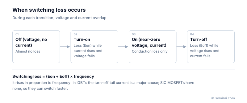
Switching loss vs conduction loss
Total device loss is the sum of conduction loss and switching loss. Conduction loss depends on the on-state resistance or voltage and grows with the square of the current, but not with frequency. Switching loss is roughly (Eon + Eoff) multiplied by the switching frequency, so it grows in direct proportion to how often the device switches.
At low frequency conduction loss dominates; at high frequency switching loss does. Designers choose the operating frequency as a compromise: higher frequency shrinks inductors and capacitors, but every extra kilohertz adds switching loss that must be removed as heat.
Why device type matters
In an IGBT, much of the turn-off loss comes from the tail current: minority carriers stored in the drift layer keep conducting until they recombine. This is a main reason why high-power IGBT inverters typically run at around 20 kHz or below. A SiC MOSFET conducts with majority carriers only, has no tail current and therefore a much lower Eoff, which allows operation at tens or hundreds of kilohertz.
Switching loss also depends on the circuit. A lower gate resistance makes switching faster and cuts loss, but raises dv/dt and di/dt, which increases voltage overshoot from parasitic inductance and electromagnetic interference (EMI). Finding the right balance is the core of gate-driver design.
Japanese companies involved
- ROHM and Fuji Electric publish switching-energy data and application notes for their SiC and IGBT devices so that designers can estimate losses in their own circuits.
- ROHM · SiC and silicon power devices, analog ICs
- Fuji Electric (power semiconductors) · IGBT modules and SiC power devices
FAQ
How is switching loss measured?
Usually with a double pulse test. The voltage and current waveforms during each transition are multiplied and integrated over the switching interval to give Eon and Eoff at a given current, voltage, temperature and gate resistance.
What are soft-switching techniques?
Circuits such as LLC resonant converters arrange for the switch to turn on when its voltage is already near zero, or turn off when its current is near zero. Because voltage and current then barely overlap, switching loss drops sharply and frequency can be raised.
Does faster switching always help?
It reduces loss in the device, but higher dv/dt stresses motor winding insulation, increases ringing and EMI, and can cause false turn-on through the gate-drain capacitance. Faster switching therefore needs careful layout and filtering.
Related pages
- Power Semiconductor
- IGBT (Insulated Gate Bipolar Transistor)
- SiC MOSFET (Silicon Carbide MOSFET)
- DC-DC Converter
- Wide Bandgap Semiconductor (WBG)
- Power Module
- Reverse Recovery
- Body Diode
- Power device test systems
- Power semiconductor manufacturing equipment
- Advantest EXAVIS
- Advantest MT100 / MT200
- Hitachi High-Tech M-600 / 6000 series
- Shibasoku ILT-1000
Sources
Last updated: November 13, 2026