Pin Electronics
Pin electronics are the circuits in automatic test equipment (ATE) provided for each pin of the chip under test. They combine the functions of driving signals, receiving and judging outputs, and forcing and measuring current. Mounted on boards in the test head, often for hundreds to thousands of pins, they set the accuracy and speed of the tester.
Also called: pin electronics card, PE
Diagram
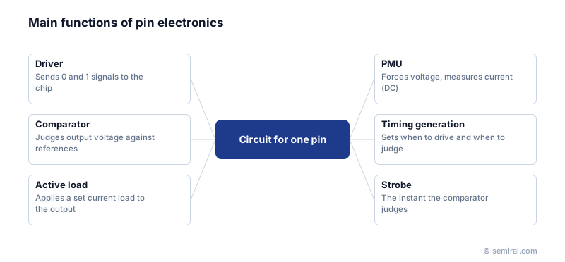
The four main functions
Each channel has a driver, which applies defined high and low voltages (logic 1 and 0) to the device. A comparator decides whether the voltage coming out of the device is above or below reference thresholds. An active load draws or sources a set current from the device output to simulate the circuit it will drive. A parametric measurement unit (PMU) forces voltage and measures current, or forces current and measures voltage.
Timing generators set when the driver changes state and when the comparator samples the output; the sampling instant is called the strobe.
How they are used in tests
In digital functional tests the drivers apply the test vectors and the comparators check the outputs against the expected values cycle by cycle. In DC parametric tests the PMU measures leakage current, output voltages and similar values. Some testers have a PMU on every pin; others share one among several pins to save cost.
As devices get faster, pin electronics must handle higher data rates, finer timing accuracy and precise low-voltage levels. These demands are met with dedicated integrated circuits designed by tester makers, which pack several channels into one chip.
Japanese companies involved
- Advantest develops the pin electronics for its own SoC and memory test systems, including the timing and measurement circuits on each channel.
- Advantest · Automated test equipment (ATE) for SoC and memory
FAQ
What does the PMU in pin electronics do?
It performs DC measurements on a pin: it can apply a voltage and measure the resulting current, or apply a current and measure the voltage. This covers leakage, input current, output voltage and contact (open/short) tests. A per-pin PMU allows these measurements on all pins in parallel, which saves test time.
What is the difference between the driver and the comparator?
The driver sends signals from the tester into the chip at specified high and low voltages. The comparator works in the other direction, sensing the chip's output voltage and deciding whether it represents a 1 or a 0. Together they let the tester stimulate the device and check its response.
Related pages
Sources
Last updated: November 13, 2026