Test Vector / Test Pattern
A test vector, or test pattern, is the data that lists, for each clock cycle, the values to apply to each input pin of a chip and the values expected at each output pin. Automatic test equipment (ATE) applies the inputs cycle by cycle, compares the outputs with the expected values, and fails the chip if any comparison does not match.
Also called: test vector, test pattern, STIL
Diagram
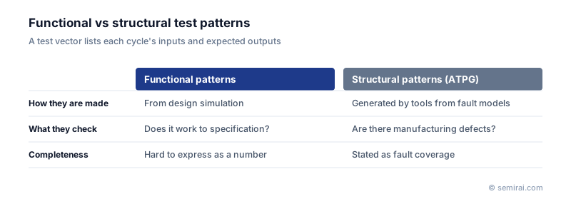
Functional and structural patterns
Functional patterns are taken from design verification: the inputs and outputs recorded in simulation are converted into tester format. They exercise the chip close to real operation, but there is no measure of how many manufacturing defects they would detect.
Structural patterns are generated by ATPG (automatic test pattern generation) tools, which assume scan chains are present. They target fault models such as stuck-at and transition faults, so their fault coverage can be stated as a number. For modern logic chips, structural patterns are the main approach, with functional patterns used for specific checks.
Formats and data volume
Patterns move from design to test in standard formats. STIL (Standard Test Interface Language), standardised as IEEE 1450, is widely used, as are the older WGL format and VCD files that record simulation waveforms. These are converted into each tester's own format and built into the test program. Agreeing on formats and timing definitions between the design and test teams avoids many problems when production starts.
In large SoCs, the volume of pattern data becomes a problem: patterns may not fit in the tester's vector memory, and test time grows. Test compression, which decompresses data on the chip, cuts the data sent from the tester by tens of times, and built-in self-test (BIST) generates patterns inside the chip. The amount and quality of test vectors therefore decide both fault coverage and test cost.
Japanese companies involved
- Advantest's automatic test equipment stores test vectors in its pattern memory and applies them to each chip in wafer and final test.
- Advantest · Automated test equipment (ATE) for SoC and memory
FAQ
What is the difference between a test vector and a test program?
Test vectors are the data: inputs and expected outputs. The test program is the software that decides at which voltages and timings to apply them, in what order to run tests, and how to judge and bin the results. Vectors are one component of the program.
What does test compression do to the vectors?
It adds a decompressor and a response compactor on the chip, so the tester sends and receives far less data than the chip actually uses internally. This saves tester memory and test time and is standard in large SoC testing.
Related pages
Sources
Last updated: November 13, 2026